I like to use the GB3US repeater located on the Met Block of Sheffield University on West St. in Sheffield city centre. The only poblem being that where I'm located in Sheffield makes it very difficult to get into the repeater with the 2/70 co-linear that I use for VHF/UHF. After some research and investigation I decided to erect a Yagi-Uda beam to give me gain and direction towards the GB3US repeater.
As I really enjoy the construction side of the amateur radio hobby I thought I'd have a go at building my own antenna. I've never built an antenna before so this is my first go and I thought I'd document my attempt on this web page.
After much surfing of the net and reading of books I decide that a I'd buy a kit from Nuxcom.de in Germany. I say kit...it's really the materials and design that you purchase. You have to measure, cut and drill all the material yourself and then complete the assembly...suits me down to the ground. The kit I chose was the DK7ZB 7 element 70cms 50/50.
The kit form Nuxcom took four days to arrive from the date of ordering, pretty good going I thought. It cost less than £38.00 including postage and packing. I couldn't source the materials in the UK for that price. Hunting around for the best deals etc. in the UK and putting on the VAT and postage took the price close to £50.00. Nuxcom provided the lot in one parcel, for one price. After I placed the order with Nuxcom, Attila Kocis (the proprietor) emailed me with postage costs to the UK and asked for confirmation of the order. If I didn't like the cost of postage I could cancel, no payment need be made if I wasn't happy with the price.
With the order confirmed, Attila sent an invoice and I paid by PayPal. Four days later the kit was with me. Everything well packaged and with a comprehensive parts list to check against, everything was accounted for. The parts list is in German but it was easy to use the Nuxcom website and check part numbers from the parts list against descriptions which are in English on the website. The construction details that come with the kit are printed A5 in black and white and the pictures are not the easy to see. However, there is a fully colour pdf available from Nuxcom. I downloaded a copy for my own future reference, it's much easier to read than those that came with the kit.
Having checked the shipping manifest and downloaded and read the construction details, I got together the tools needed to complete the project.
The cutting and drilling needs to be high quality and accurate. I used the following tools and equipment.
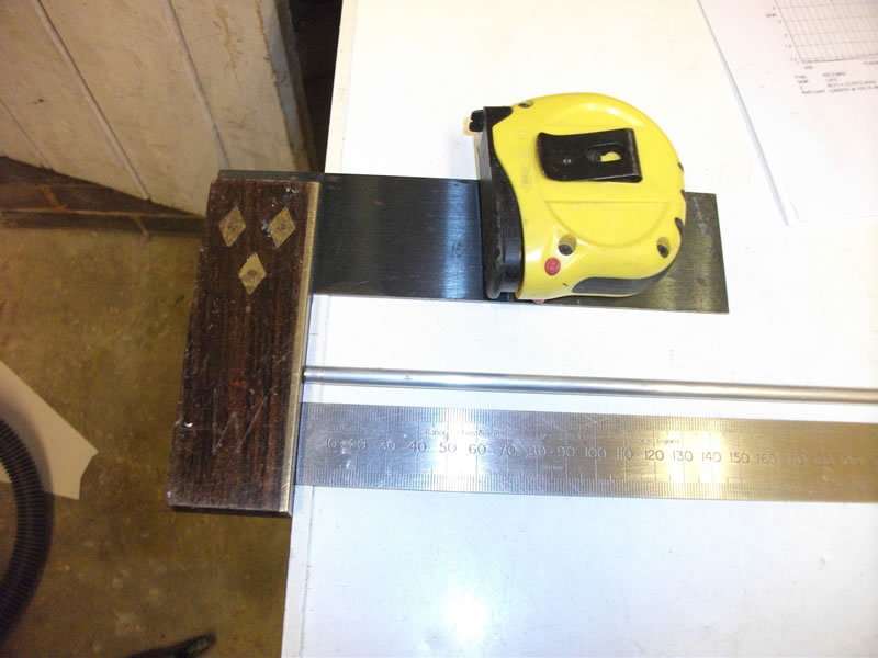
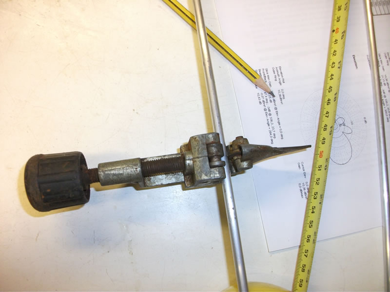
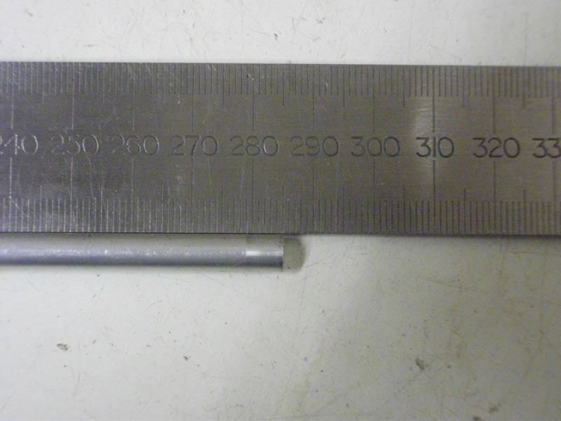
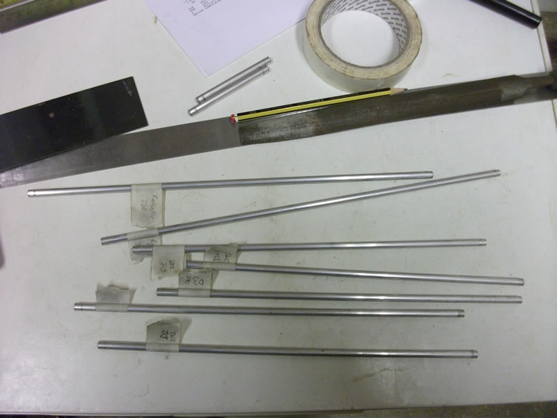
The first components that need to be manufactured are the elements, reflector and radiator. Each of these parts are different sizes. Each of these elements is cut from 6mm tube. I marked out an element using a sharp pencil, steel rule and a try square and then cut the element from the supplied tube length using a pipe cutter. The elements were cut slightly longer. Each element was checked for length and final adjustments to the length were made using a file. Labels were stuck to each element to aid indentification.
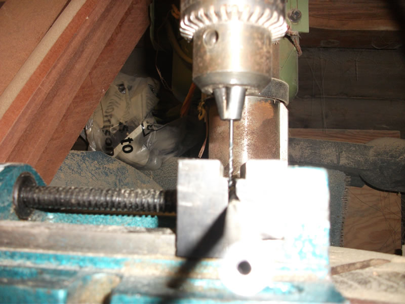
The elements were drilled using a pillar drill and machine vice. Care had to be taken to set the machine vice so that the element was drilled centrally across its 6mm diameter. You can see from the photos that the machine vice has one flat jaw and one 'V' jaw. The element was clamped into the vice and the vice set so that the flat jaw of the vice was touching the edge of a 2mm drill bit - this was my datum for finding the centre of the tube diameter.Using a little bit maths I knew that the centre of my 2mm drill bit was 1mm from the flat jaw of the vice. To get the centre of my drill bit to the centre of the tube diameter I tapped the vice gently across the table of the pillar drill, only a small amount of movement was needed - 2mm in fact to get the centre of the drill across the centre of the tube diameter. I clamped the vice down to the drill table and changed the drill bit to 3.5mm (the size needed for the fixing). I could now drill each element at half its length.
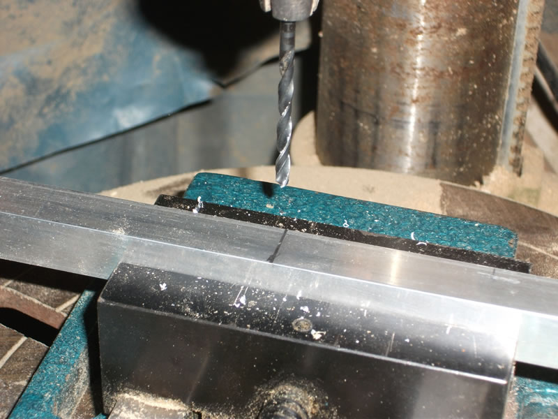
Starting at the position for 'director 5' and working backwards towards the reflector, each hole to be drilled was marked-out continuously along the length of boom using a tape measure. Using this method of measuring avoids the 'cumulative error' that can occur if you measure from element to element.
The boom was placed in the machine vice on the drill table and the centre of the boom found in a similar way to that used with the elements.. Once the holes were drilled the element supports and elements were positioned on the boom and the elements secured using the 3.5mm nuts and bolts supplied. Be careful not to over tighten the elements; I over tighten one and fractured the element, resulting in a broken element requiring replacement.
A choke was wound using the supplied RG188 and 16mm PVC tube. 3.5mm holes were drilled through the PVC tube to help keep the choke windings in place. Further support for the choke windings was provided by using a cable tie through the PVC tube and secured around the windings. The choke requires between 5 and 7 turns of the RG188 around the tube.